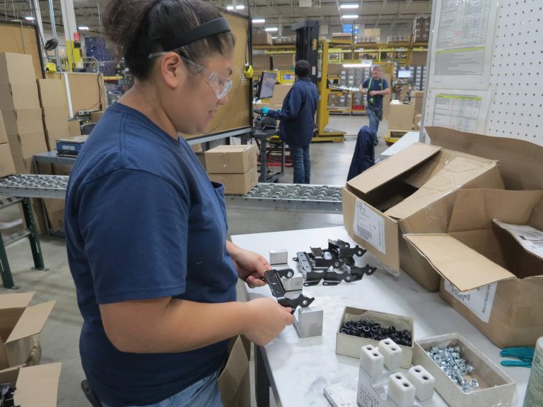
This video highlights a manufacturing process improved at our Minster 300-ton stamping press utilizing sensor technology that was designed and built by our Automation Technician, Andrew.
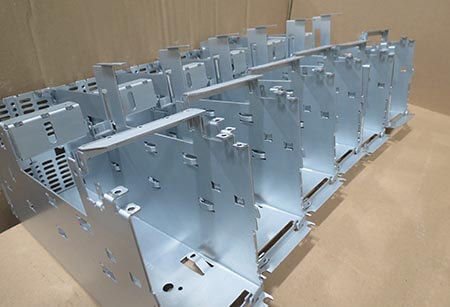
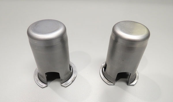
The press operators identified an opportunity to increase production rates for these metal head covers from 30 strokes a minute to 35 strokes a minute. The primary roadblock preventing this increase was the capacity of the washing station after the metal stamping. The head covers needed to enter the washing station with adequate spacing between each other and at a consistent rate on the conveyor belt.
Plan of Action
Install a longer conveyor belt utilizing automation and sensor technology to control the alignment of the head covers and maintain a steady rate into the washer.
A total of three cylinders were determined to be the best actuators for performing the following operations.
- Diverting the head covers on the conveyor belt
- Positioning the head covers correctly
- Controlling the rate the head covers are entering the washer
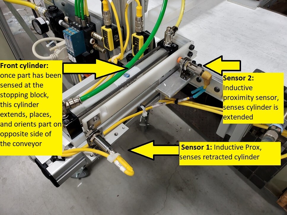
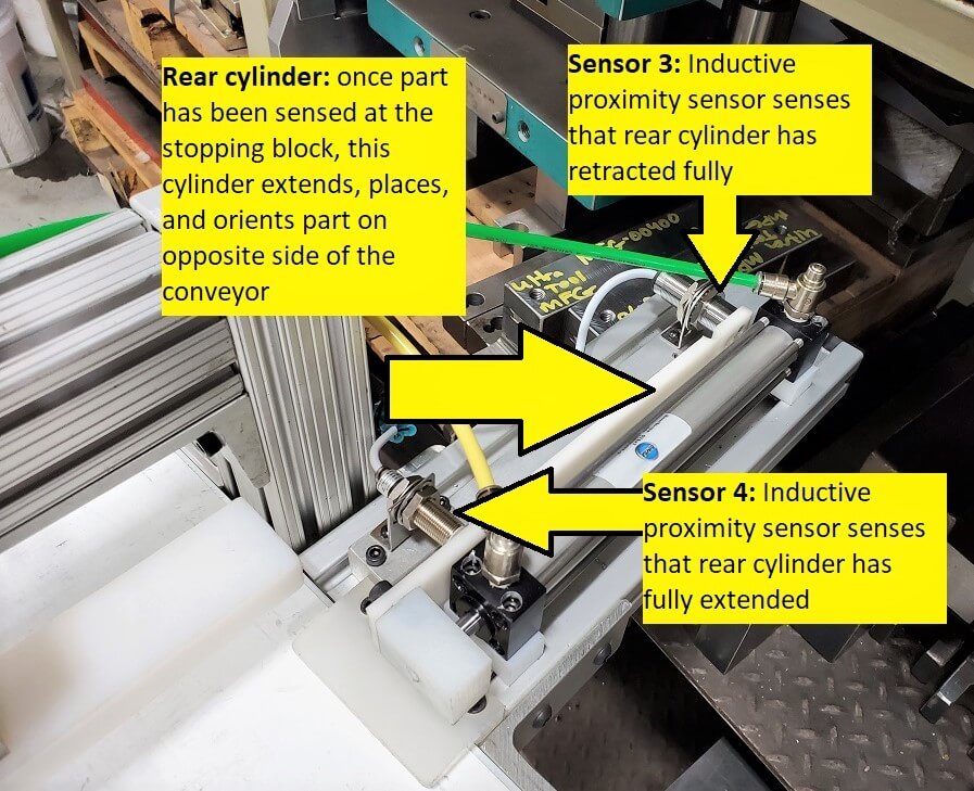
The two side cylinders operate opposite of each other and push a head cover into position on the conveyor belt while maintaining a consistent rate. Then a single “guided thrust” cylinder extends downward to temporarily stop and orient the part. It then retracts to allow the correctly oriented head cover to pass through to the washing station.
How do the cylinders perform these operations?
A PLC (Programmable Logic Controller) communicates to each cylinder to extend or retract; and the PLC receives this information from the NINE SENSORS in the automation station.
Types of Sensors
Each of the three cylinders has (2) Inductive Proximity Sensors that detect ferrous material (any material containing iron) and also sense that if the cylinder is either fully retracted or fully extended
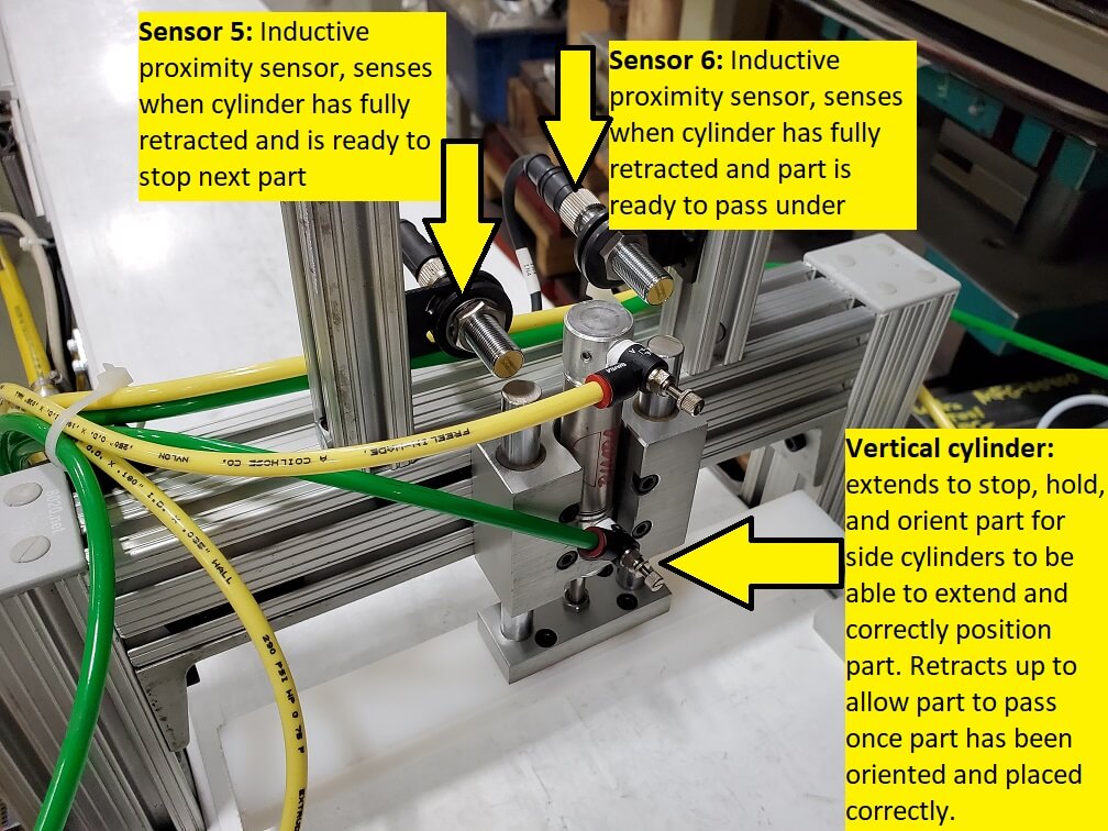
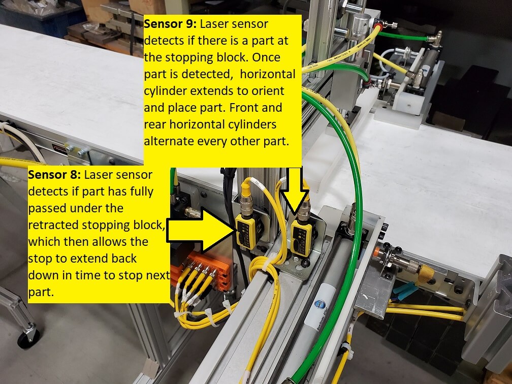
There is (1) Laser Sensor that detects when a head cover has arrived at the stopping block, which then tells one of the side cylinders to extend and push the head cover into place. After this occurs, the top cylinder retracts to allow the head cover to go under the stopping block.
There is (1) Laser Sensor that detects that a head cover has fully passed under the retracted stop block and signals the stop block to return back down into a “stopping position”.
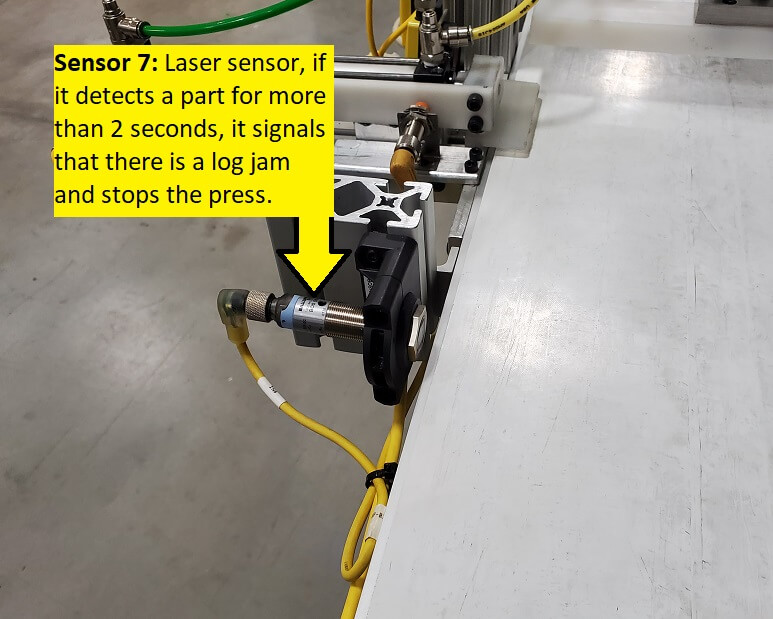
There is (1) Laser Sensor (located a few feet before the other sensors and cylinders) that detects a log jam if it sees a head cover for longer than two seconds.